
Buderus oil- and gas-fired boilers were designed and built according to latest technologies, safety regulations applicable for commercial and industrial use boilers and therefore Buderus boilers need to be installed by qualified specialists. Read and obey all the safety instructions and the operator’s instructions thanks to which you will be able to provide economical, safe and environmentally-friendly appliance usage. Buderus oil- and gas-fired boilers ware designed for the heating of central heating water and hot water to the taps. These boilers are operated with the 2000 or/and 4000 series control systems. After your boiler is successfully commissioned, person responsible for installation will write down the exact type of fuel for your system into the service book/ user’s manual.
Wall clearances
Where possible install the boiler with the recommended wall clearances (values shown table below). Remember that reducing the minimum clearances makes the boiler more difficult to access for safety and service purposes.The foundation where boiler will be standing needs to be level and flat.
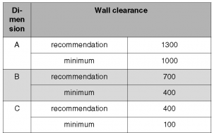
Whenever applicable an extra wall clearances for additional components should be provided, especially in instances where pipe connections, DHW cylinder and flue gas silencer are located on the flue gas side.
Safety first!
Inappropriate operation of Buderus boilers may lead to material losses, heath and life danger:
- Life danger- through the explosion of volatile gases. If you can smell gas then there is a risk of explosion. Avoid any source of sparks, don’t use any electrical switches, mobile phones, door bells etc. Keep away from any naked flames, don’t use lighters. Then you should close the mains gas, and that can be achieved by closing off the mains valve, immediately open all doors and windows. Warn all people being at the property and leave the building. Contact your gas supplier by using a phone minimum 100 m away from your property. If necessary, notify police or fire services. Leave the danger zone immediately when you hear gas streaming out
- Life danger- through poisoning. Ventilation not good enough can lead to dangerous flue gas leaks. Make sure that the ventilation and exhaust air openings are not closed and not restricted. You should switch off the boiler immediately and call for help
- Life danger- through the explosion of volatile gases. Make sure that the installation, fuel gas and oil connections, the initial start-up, the power connection, repair and maintenance work are carried out by licensed specialists
- Life danger and material losses- through the fire of the combustible material or liquids. Never store flammable materials or liquids next to heat generator
- Material losses- through boiler damage caused by contaminated combustion air. Never use chlorinated cleaning agents or halogenated hydrocarbons (as, for example paints and adhesives, solvents or cleaning agents, contained in spray cans). Avoid atmospheres which are frequently very dusty. Never hang washing to dry in the boiler room
- Material losses- through system damage caused by frost. Make sure that the boiler room is always free from frost
- Material losses- through system damage caused by not proper maintenance and/or cleaning. Have your system inspected, cleaned and maintained annually by a specialist. Annual service record should be entered into operating manual book provided with your boiler
Remember to:
1. Operate the boiler only as intended and when it is in perfect condition
2. Don’t install the boiler yourself, let it to a heating engineer
3. Book the time at the end of installation and commissioning so that heating engineer can train you properly in boiler’s operation system
4. Read the users manual carefully
Buderus system boilers operation
Proper water need to be filled into the Buderus boiler system. Water present in the heating system is the heat transferer. Depending on its purpose, water can be divided into different groups: heating water is the medium contained within your heating system, fill water is medium used for first system filling- before it is commissioned. The pre-treated water normally used for the system topping is called- make up water. It is very important that the water keeps high quality at all times. Any water contains substances like calcium hydrogen-carbonate which is influencing the heating system functioning. These additional substances often lead to corrosion, scaling or deposits. Annual check is required in order to verify if the water quality is good enough and if not make-up water needs to be added. Usage of proper water results in economical system usage as well as its energy efficiency and operational reliability.
Buderus boiler maintenance and annual service
In order to assure proper economical functionality (low fuel consumption) and high level operational reliability your boiler should be serviced annually. During the annual service your boiler will be cleaned, used parts will be replaced and the whole system will be refilled with make up water and air vented. You will also maintain the highest level of environmentally responsible combustion
Fault finding
Heating system and hot water faults are indicated in the control unit display. Detailed information about faults meaning can be found in the tables below. We recommend to use those tables for proper communication with Buderus customer service or boiler service engineer. Additionally any burner fault is indicated by a fault lamp on the burner. Remember not to damage the system through frequent activation of the reset button. The burner ignition transformer may get damaged once you press the reset button more than three times one after another when burner refuses to start. Don’t try to clear a fault more than three times in succession by using the reset button.
The display value is shown automatically or can be called up by pressing the “Service” button. Two display codes will also be shown. After the first display code is shown the second one should be called up by pushing the “Service“ button. On the BC10 basic controller level 4 can only be called up in the event of a fault code. Under normal operating conditions it is only possible to call up level 4 using the RC control device or a service tool. In instances where the display code is a fault code, this fault code either flashes (locked fault code) in the display or it is shown permanently (blocking fault code). A boiler reset is only necessary with a locking fault code (flashing). The cause of the fault must be remedied first. The cause has to be remedied and the boiler resumes regular operation. In the event of a locking boiler fault code both the display value and the display code flash. If there are more than once display codes at the same time, the display codes will be shown in turn. And if one of these display codes is a locking display code, the blocking display codes shown will also flash.
Table 1.Buderus boilers locking- fault codes applicable for all models
| Display code | Fault | Action |
| – | No communication between UBA 3 and BC10. | Press the “Reset” button, if fault persist contact your installer |
| 0 Y 276 | The supply sensor has measured a temperature higher than 203 °F (95 °C) |
Open the servicing cocks. Fill and bleed the heating system. Open a thermostatic valve. Replace the supply, safety and/or return sensors. Replace the primary circulation pump
|
| 0 Y 277 | The safety sensor has measured a temperature higher than 203 °F (95 °C). | |
| 0 Y 285 | The return sensor has measured a temperature higher than 203 °F (95 °C) | |
| 1 L 211 | The UBA 3 does not register any connections to the unused contacts 78 and 50. | Restore the contact between the UBA 3 and the UBA 3 mounting base |
| 2 E 207 | The system pressure is too low. | Fill and bleed the heating system |
| 2 F 260 | No temperature increase after burner start or the temperature difference between the supply and safety sensors is more than 27 °F (15 K) |
Open the servicing cocks. Fill and bleed the heating system. Open a thermostatic valve. Replace the supply and/or safety sensors. Replace the primary
circulation pump |
| 2 F 277 | The temperature difference between the supply and safety sensors is more than 27 °F (15 K) | |
| 2 L 266 | The primary circulation pump does not generate a pressure difference | Try to undo the jam or replace the primary circulation pump. Replace the primary circulation pump. Replace the supply cord. Clean the circulation pump (inside). Connect the expansion tank to the return conduit. Clean the pressure sensor. |
| 2 P 212 | Temperature increase of supply sensor or safety sensor is more than 7.5 °F/sec (5 K/sec) | Open the servicing cocks. Fill and bleed the heating system. Open a thermostatic valve. Replace the supply and/or safety sensors. Replace the primary circulation pump |
| 2 U 213 | The temperature difference between the supply and return sensors is more than 90 °F (50 K) | Open the servicing cocks. Open a thermostatic valve. Replace the supply and/or safety sensors. Replace the primary circulation pump |
| 3 A 264 | The air fan has failed during the operating phase. | Reconnect the plug-and-socket connection of the blower. Replace the tacho wire. Have the electrical system tested. Replace the supply cord. |
| 3 F 273 | The blower is switched off during the safety test | Fully switch off the heat request and check that the blower is still operational after 1 minute. Replace if necessary |
| 3 L 214 | The blower is switched off during the safety test | Reconnect the plug-and-socket connection of the blower. Replace the tacho wire. Have the electrical system tested. Replace the supply cord. |
| 3 P 216 | The blower is running too slowly | Clean or replace the blower. Have the electrical system tested. |
| 3 Y 215 | The blower is running too fast | Restore the plug-and-socket connection. Replace the tacho wire. Have the electrical system tested. Deal with blockage. Take the second blower out of service. Replace the blower |
| 4A 218 | The supply sensor has measured a temperature higher than 221 °F (105 °C) |
Open the servicing cocks. Fill and bleed the heating system. Open a thermostatic valve. Replace the primary circulation pump. Replace the supply and return sensor
|
| C A 286 | The return sensor has measured a temperature higher than 221 °F (105 °C) | |
| 4C 224 | The UBA 3 does not register the short cut between the unused contacts 22 and 24 | Restore the contact between the UBA 3 and the UBA 3 mounting base. |
| 4E 278 | The sensor test has failed | Replace the cable loom or the affected part thereof |
| 4L 220 | The safety sensor is shorted or measures temperatures higher than 266 °F (130 °C) | Open the servicing cocks. Fill and bleed the heating system. Open a thermostatic valve. Replace the primary circulation pump. Replace the cable loom or the affected part thereof. Replace the safety sensor |
| 4P 227 | The safety sensor contact is interrupted | Replace the cable loom or the affected part thereof. Replace the safety sensor |
| 4U 222 | The supply sensor contact is shorted |
Replace the cable loom or the affected part thereof. Replace the supply and return sensor
|
| C U 240 | The return sensor contact is shorted | |
| 4 Y 223 | The supply sensor contact is interrupted |
Replace the cable loom or the affected part thereof. Replace the supply and return sensor
|
| C Y 241 | The return sensor contact is interrupted | |
| 6 A 227 | No ionization after four startup attempts | Contact the gas utility company to ensure that no nitrogen remains in the gas tank or gas supply pipes. Bleed the gas supply pipe. Replace the hot surface ignitor. Adjust the gas/air ratio. Fit the correct gas orifice. Clean and/or replace the corresponding components. Deal with blockage. |
| 6 C 228 | An ionization current was measured before the burner start. | Replace the ionization electrode |
| 6 C 306 | An ionization current was measured after the burner switch-off | Replace the gas valve |
| 6 L 229 | Ionization fails during the operating phase | Ensure that no nitrogen remains in the gas tank or gas supply pipes, in close consultation with the gas utility company. Bleed the gas supply pipe. Adjust the gas/air ratio. Clean and/or replace the corresponding components. |
| 6 P 269 | The hot surface ignitor activates too long | KIM defective, contact the Buderus customer service |
| 7 C 231 | The power supply was interrupted after a fault message | Press the “Reset” button, if fault persist contact your installer |
| 7 L 261 | The UBA 3 is defective |
Contact the Buderus customer service or your installer
|
| 7 L 280 | The UBA 3 is defective | |
| 8 Y 232 | The external switch contact is activated | External switch contact has energized. Replace the cable loom or the affected part thereof. Restore the contact. Restore the bridge on the terminal strip again |
| 9 A 235 | KIM or UBA 3 is defective |
Contact the Buderus customer service or your installer
|
| 9H 237 | KIM or UBA 3 is defective | |
| 9 P 239 | KIM or UBA 3 is defective | |
| 9 U 233 | KIM or UBA 3 is defective | |
| E 242-287 | KIM or UBA 3 is defective | |
| E 290 | The UBA 3 is defective. | |
| 9 L 234 | The gas valve coil or the wiring to the gas valve is defective |
Restore the plug-and-socket connection. Replace the cable loom or the affected part thereof. Replace the gas valve
|
| 9 L 238 | The UBA 3 is defective | |
| C 0 288 | The UBA 3 has no connection to the pressure sensor or there is a short circuit |
Restore the plug-and-socket connection. Replace the cable loom or the affected part thereof. Replace the UBA 3
|
| C 0 289 | Short circuit in connection to pressure sensor |
Attention! Buderus boilers require a correct fuel to ensure a proper operation. Especially because the statistics show that Buderus boiler faults occur mostly due to two reasons
- wrong installation and commissioning
- wrong or dirty fuel
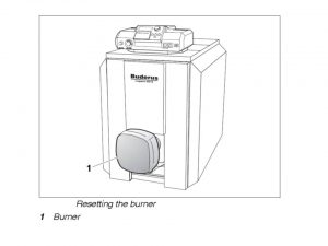
Remedying burner faults
As mentioned above there are two types of faults burner faults and the control device and heating system faults. Whenever there is a burner fault, the lamp located on the burner will flash. In most cases those faults can be remedied by simply resetting the burner/ resetting the appliance (look below procedure on how to reset the boiler). Heating system faults/errors will be displayed on the display of the control device. Control device and heating system fault finding is included in the section above. To remedy burner faults you should remove the burner hood, if the boiler has an integral burner. Next you should press the burner reset button as shown on the picture below
Buderus boiler systems- water pressure check
Buderus boilers are able to work in two systems: sealed and open. Nowadays sealed system boilers are commonly used, and open systems are usually boilers that were commissioned 5-10 years go. Therefore, a sealed system is used as an example of how you can check the water pressure.
The pressure gauge marker in case of sealed systems must be within the green field. Ensure that the red pressure gauge needle is set to the required operating pressure. Set the over-pressure to at least 1 bar. Check the heating system operating pressure.
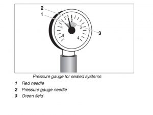
If the operating pressure is too low (the pressure gauge needle indicates below the green field) top the system up with water. Top up with water. Bleed the heating system. Re-check the operating pressure.
Attention! You can damage the system if you re-fill it too frequently due to water quality or by corrosion and scaling. You should contact your installer or service engineer if you need to regularly re-fill the system as there may be a leakage in the system and leak testing should be performed, because pressure, control and safety equipment may be damaged through excessive pressure.
If you carry out a leak test, you need to make sure that no pressure, control or safety equipment is fitted which cannot be isolated from the boiler water chamber. Shut off the pressure expansion vessel from the system by closing the cap valve. Then verify the connections and pipework for leaks. After this the mixing valve should be opened as same as the shut-off valves- both on the primary side- hot water. At the end system should be re-filled with water.
Refilling the system
Each heating system need to contain proper amount of water to function correctly. Make-up water should be added into the heating circuit when the system pressure is not high enough. In most cases make-up water loses much of its volume in the first few days because of gases release. If you are a new system owner we would recommend to check your heating system water pressure first on a daily basis, and thereafter at increasing intervals. Otherwise system pressure should be checked pressure monthly, if the heating system still loses volume. Sometimes you can experience air pockets accumulation caused by re-filling and therefore the whole system should be air-vented through the radiators.
Operating conditions on Buderus G and GE cast iron boilers
One of the most unique features of the Buderus iron cast boilers is the thermo-stream technology. The main idea of this technology is that the water that comes to the combustion chamber is first preheated and then mixing within the appliance. Thanks to this there is a sustainable temperature distribution and there is no condensate built int he combustion chamber. This way thermal stress is highly reduced. The minimal appliance operating temperature is always maintained- no need for a pump, n risk of its breaking. The minimum appliance operating temperatures are listed in the table below. Those temperatures should be reached within maximum 10 min period of time.
Table 3. General operating conditions
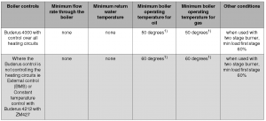
Table 4. Fuel operating conditions
Fuel operating condition can be easily achieved by the controls monitoring the boiler temperature and reducing the flow rate through the boiler until the required temperature is reached. This is can be kept by controlling flow comparing to temperature of the boiler. Flow rate can be reduced by modulating the boiler primary pumps, closing the valves on the mixed heating circuits. Normally it can be managed by the Buderus 4000 control panel, but that can also be achieved by simple BMS usage.
In those cases where it is difficult to regulate the proper flow, fitting a shunt pump circuit is recommended. In the most the cases the shunt pump circuit can be controlled normally by Buderus 4212 fitted with a ZM427 module or Buderus 4000 control.
Leak test
1. Preparing for a leak test- close all boiler hubs, the flow and return connections (fit the air vent valve to the connecting block Rp 3⁄4
2. Carry out a leak test at a test pressure of 5.8 bar (in accordance with the requirements of the European Pressure Vessel Directive). Slowly fill the boiler block. Bleed at the highest point of the system, until water flows out of the air vent valve.
Leaking hub joints
If you suspect the hub joint leaking you need to primarily drain the water through the fill & drain valve. Then remove the water pipes and the the feed pipe. After this release and remove the anchor rods. Separate the leaking boiler by driving flat wedges or chisels into the leaking part.
Attention Pressure gauge class 1.0 should be used for the pressure test purposes. Remember that system may get damaged through over-pressure. You need to make sure that no pressure, control or safety equipment is fitted. Slowly fill the boiler block. Bleed at the highest point of the system, until water flows out of the air vent valve. Hubs need to be cleaned before re-assembly.New nipples shouldbe used and and new packing cord. Your appliance should be compressed block again. The feed pipe and the anchor rods need to be re-fitted and at the end the leak test should be repeated
Parts replacement
The UBA 3 fuse replacement
1. Switch off the power supply of the heating system on the circuit breaker
2. Set the main switch on the BC10 to “0” (Off)
3. Remove the casing
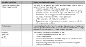
4. Loosen the fastening screw of the UBA 3 by turning it counterclockwise as shown on the picture below
5. Remove the UBA 3 once the fastening screw is fully loosened by pulling it forward carefully as indicated by the arrow
6. Dismantle the fuse holder by loosening the bayonet connector
7. Remove the fuse from the fuse holder
8. Check the circuit continuity through the fuse using the volt-ohm multimeter. If broken, replace it by (a new) spare ceramic fuse 5 amps, 250V fast blow (F5AH, 250V)
9. Re-assemble the UBA 3 in reverse order of disassembly
10. Fasten the UBA 3 by only turning the fastening screw clockwise. Fit the casing
11.Switch on the power supply of the heating system on the circuit breaker
12. Set the main switch on the BC10 to “1” (On).
Attention! Do not pull or move side to side the UBA 3 during loosening or tightening of UBA 3 fastening screw! Do not push or force the UBA 3 in place by hand!
External connection board fuse replacement
1. Switch off the power supply of the heating system on the circuit breaker
2. Set the main switch on the BC10 to “0” (Off)
3. Remove the casing
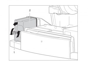
4. Remove the cover from the connection box as shown on the picture below
5. Dismantle the fuse holder
6. Remove the fuse from the fuse holder
7. Check the circuit continuity through the fuse using the volt-ohm multimeter. If broken, replace it with a (new) ceramic fuse 5 amps, 250V fast blow (F5AH, 250V)
8. Re-install the cover on the connection box
9. Fit the casing
10. Switch on the power supply of the heating system on the circuit breaker
11. Set the main switch on the BC10 to “1” (On)
Boiler cleaning
1. Shut down the heating system
2. Remove the burner door casing or the burner hood from the boiler itself
3. Pull the burner plug off the burner
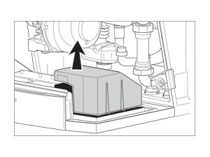
4. Clean the boiler with brushes and/or by a wet method. To clean your boiler properly you should first open the door by removing the two lateral hexagon bolts.
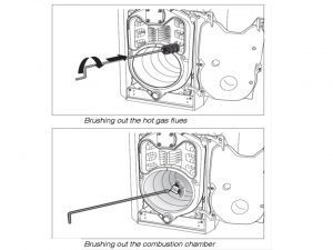
Cleaning the boiler with cleaning brushes
First you should write down the position of the hot gas baffle plates to ensure their correct re-installation later. Next you should remove the hot gas baffle plates from the hot gas flues. Now you should clean the hot gas baffle plates using one of the two cleaning brushes as shown on the picture below. The hot gas flues should be cleaned by rotating the round cleaning brush. Combustion chamber should however be cleaned with a flat brush. All loose combustion residues need to be removed from the combustion chamber, the flue outlet and the hot gas flues
Now the hot gas baffle plates need to be installed as same as in their original position. Verify position of the packing cord on the burner door. Hardened or damaged packing cord must be replaced!
The burner door should be closed with both hexagon bolts. Tighten the hexagon bolts evenly to properly seal the burner door.
Wet cleaning (chemical cleaning)
When wet-cleaning, proper cleaning agent level should be used (appropriate to the level of contamination- soot level and encrusted residues). While wet-cleaning you should follow the same steps in the same order as described for cleaning with brushes, but you need to pay attention to the cleaning agent functionality, in some instances you will need to cover the control device with plastic to prevent spray from entering the control device. The cleaning agent should be spayed evenly into the hot gas flues. The burner door should be closed the burner plug should be plugged and now you should start the heating system. The heating water temperature need to be minimum 70 °C. Once achieved you can shut down the heating system and brush out the hot gas flues.
Stating up the boiler
Before you start the boiler make sure that: the system water pressure is at the proper level, emergency stop switch of the the heating system is ON and the fuel supply to the main fuel shut-off valve is open
Restarting the boiler
In order to reset the boiler you need to simply press the burner reset button. Remember that you can damage the system through frequent activation of the reset button. The burner ignition transformer may get damaged once you press the reset button more than three times in one after another if burner refuses to start. Don’t try to clear a fault more than three times in succession by using the reset button.
System shutdown
Your heating, hot water boiler may be switched off when it won’t be use for a longer period of time (weeks, months). Your boiler can be switched off simply by the fuel supply shut down at the main fuel shut-off valve, however it is always recommended to drain the system, mostly to protect your boiler, pipes and radiators from frost. water should be drained always at the loest system point via cut draining valve. The air vent valve should be opened at the highest system point. The system can freeze up if it is not in use, e.g. through a shut-down because of fault(s). It is advice to protect your system against frost damage, where temperatures below zero are expected
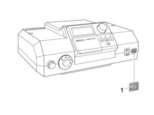
The heating system shutdown Logamatic 2000
1. Switch the control device OFF/ON switch to the OFF (position “0”). This switches the boiler and all its components OFF (for example the burner) as shown on the picture below. The main shut-off fuel valve should be closed
1 ON/OFF switch
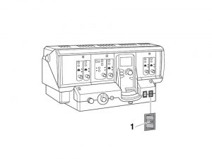
The heating system shutdown Logamatic 4000
Switch the control device OFF/ON switch to the OFF (position “0”). This switches the boiler and all its components OFF (for example the burner) as shown on the picture below. The main shut-off fuel valve should be closed
1 ON/OFF switch
Emergency shutting down the system
In other dangerous circumstances, isolate the main fuel shut-off valve and the electrical power supply of the system. This can be done at the appliance main fuse or alternatively by the the emergency stop switch.